


It all started with Dist selling me his wind deflectors – so he’s entirely to blame for what happened next.
I managed to get hold of the fog lighting kit for the phase 1 R8 – or as Rover called them in the accessories brochure in 1990 – “Fog Light Pods.”
It struck me other members might be interested in the installation and what it involves, so here goes…
First up – you need to be confident you can take the front bumper off (and put it back on again…). It caused me some head scratching but in the end I got to the bottom of it thanks to Francis and Dist through the forum. Once I knew I was okay with this side of things, it was all-systems go…
I tackled the electrical installation first, believing the mechanical side to be straightforward. In the box you get this rather interesting wiring harness, complete with its original “Tested - OK” sticker:
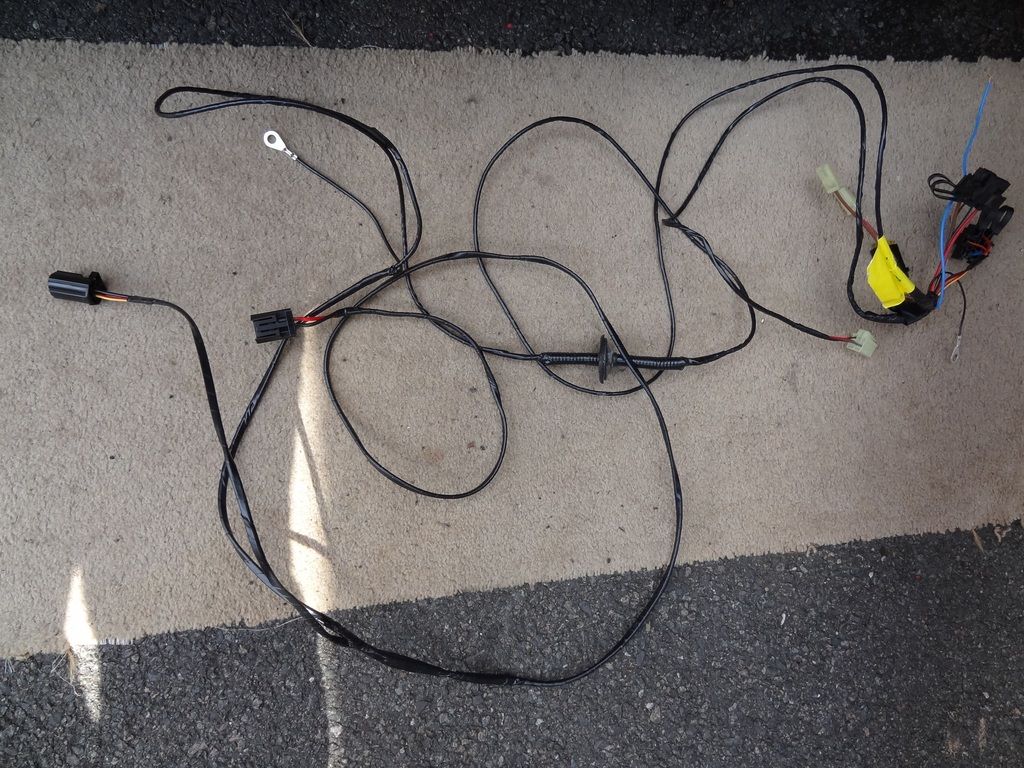
On the right of the picture, you should be able to identify two relay sockets, an Earth/ground eyelet, a 20A blade fuse (hiding under two wires that plug into the fuse box), the mysterious “blue wire” and the connector for the dash fog light switch, which you also get.
On the left of the picture you should be able to see two waterproof fog light connectors, an Earth/ground eyelet and in the middle, the grommet to protect the cable as it passes from inside the car into the engine bay.
Reading the instructions, connection of the “blue wire” into the supplementary wiring harness seemed like the trickiest job, so I tackled this first – after disconnecting the battery
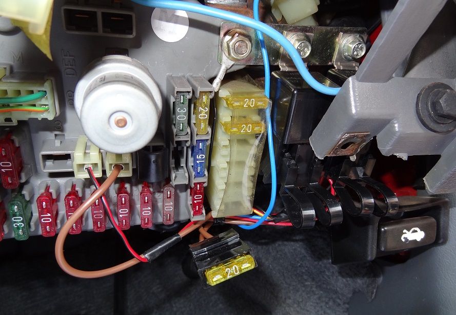
Rover provide a Duraloc connector in with the kit to do this, but quite frankly, I was so tight for space working on the fuse box that I didn’t think I could use it. The “blue wire” requires connecting to an existing blue wire on the BACK of the fuse panel, 6 wires down on the right-hand side of the largest, vertical connector in the middle. It strikes me this was somehow an afterthought to correct a mistake or something they’d missed out in the design of the fuse panel, as everything else plugs into existing sockets.
I decided to disconnect the front of the fuse panel, take out its two mounting screws and bend it down gently to see what was going on. To be honest, I had no idea British Telecom routed the entire Birmingham telephone exchange through Rover R8s. You learn something new every day, I find
The plugs on the front of the fuse box came out easily – the ones on the back didn’t want to budge. I decided I could probably solder the blue wire on carefully by parting the surrounding rats nest and fashioning a kind of heat shield to isolate it, so I didn’t melt any insulation off the rest of the loom by mistake. There was no way I could even strip the existing wire - you’ll know exactly what I mean if you have a look yourself – there’s almost no room to manoeuvre. So I melted the insulation off with the tip of my soldering iron, picked off the mess, wound the fog-light loom blue wire around the bared section and fed in some solder. Here’s the joint with my metal heat shield aluminium plate inserted to protect the test of the loom whilst I did the job.

I wrapped yellow PVC insulating tape around the joint several times. I did a couple of separate wraps to make sure it was well covered:

I then carefully righted the fuse panel, reattached it to the car with the left-hand bolt and plugged in the harnesses I’d taken out at the front. You’re supplied with two metal bars that bolt together end to end – the two relays bolt to these and then the whole thing is held in place by the right-hand fuse panel bolt which is also an Earth/ground. The Earth eyelet on the dashboard end of the loom needs to be connected in here. Finally, plug in the relay sockets on the wiring loom and the brown and red/black wires into the front of the fuse panel, all as shown below.
You can then pop out the front fog light switch cut-out on the lower left dashboard, route the switch plug and cable through it, connect the switch and push it into the dash:

The remainder of the wiring loom was then threaded under the dash, through the back of the centre console and to the passenger foot well area, where you’ll find the outlines of two cut-outs in the sound proofing if you peel back the carpet.
The smaller of the two, lower down, was too small for the fog-light connectors to pass through, so I used the larger of the two higher up that accesses a rather large rubber blanking plug just behind the washer bottle on the 1.6. I ended up cutting an “X” about 20mm corner to corner in this plug, and bolting the sealing grommet to it using M2 bolts – it was the only way I could think of achieving something fairly robust quite quickly.

The remainder of the loom then routes quite neatly along the inside face of the near-side wing, passing underneath the power steering reservoir and the coolant expansion tank on the 1.6.

Next, the high-current Earth/ground eyelet has to be connected to the lamp cluster grounding point at the front of the near side wing, shown here:

Finally, the loom can be routed down towards the front cross-member and in fact it should run in front of the radiator, at the bottom, so the two plugs reach the fog lights.
Fitting of the lights to the bumper is fairly straightforward, but does require that you cut some of the middle bar of the lower air intake away on each side, including its small vertical supporting bars in those areas.
You can place the pods onto the bumper sans the lights themselves, to see how they will fit. They can be positioned I’d say within a 50mm range of the edge of the lower air intake on each side.
Rover suggest in their instructions that you cut 180mm of the middle bar out on either side. I WOULD STRONGLY SUGGEST you cut away far less. If you cut 180mm away, you’ll have to slide the pods towards the centre of the bumper to cover the modifications. The old-fashioned look for fog lights was to have them close together in the centre of the bumper, but the modern look is to have them separated and under each headlamp, near enough. I’d suggest cutting 140mm out or even less – but make your own measurements. The pods with lamps fitted can then be positioned where just the pods themselves could be slid outwards to, before the bumper mods and lamp installation.
Here’s a picture of the near-side pod and lamp installation:

Lucky that I only cut off what I did – I could have got away with cutting far less and even possibly keeping the next vertical supporting bar on each side. Maybe. I say "cut" - the easiest way I found to modify the bumper plastic was to use an old soldering iron to melt through it slowly. You'll expend less energy doing this than sawing through, assuming you can tolerate the fumes. The lights are then a tight fit up to the edge of the bumper moulding inside, but everything works as it should, including the adjustment screw. The adjustment screw is the only true fixing for each fog light to their respective pod – the lamps clip in along the bottom edge on both sides, allowing them to tilt backwards (controlled by the adjustment screw). The lamps aren’t symmetrical of course, so on one side it’s the lamp body that will contact the bumper first and prevent you sliding it out any further. On the other, it’s most likely the tight fit of the plastic adjustment screw “nut” on the back of the lamp that contacts the bumper first. You’ll have to slide the pods out so they are an equal distance in on both sides – I measured from the number plate recess to the inside edge of each pod across the front face of the bumper and found I could get both to be in the range 50-55mm.
Here’s the offside fog light installed from the back:

Those black metal brackets you see are supplied and are held to the pods by screws from the front plate into those captive white plastic nuts, which have to be clipped in too. Rover recommends you site these brackets on the bumper first and screw them in, then attach the pods. I found it far easier to assemble the brackets to the pods first, then there are 4 holes per light to be drilled in the bumper. I marked the top two first, drilled pilots and fitted the screws. This holds the lamp in exactly the correct position to mark the lower two screw holes. The lamp can then be removed to drill pilots for these and the whole thing then finally assembled. Notice I didn’t make proper use of the connector clips on the back of the brackets – I assume the fog light connectors clip onto these to provide some strain relief for the lamp wires. I just used them to pinch the wires instead, thinking the few extra inches of free wire may be beneficial if I need to remove the pods or the bumper in the future. It turns out in fact that the loom itself is plenty long enough to allow disconnection if needed.
Here’s the completed installation on the bumper, from the front:

And finally, if you need to take the fog lights out completely – perhaps to change a bulb or the lamp itself, then the following photo from underneath one of the pods shows the 4 screws you need to remove, leaving the black mounting bracket on the car. The top two (and the screwdriver you use to remove them) will interfere with the top edge of the fog light glass, so it’s best to undo the adjustment screw completely which allows the lamp to freely tilt backwards a few degrees, providing clear access. When you come to re-install the pod, screw it to the car first, then push on the lamp from behind (with your arm over the grille) to tilt it forward, whilst turning the adjustment screw from the front, until it engages.
Note the colour difference between the Wurth Anthracite dye I used to restore my faded bumpers and Rover’s original LOY grey of the pods. Visible under flash light but not really noticeable in daylight as both greys are quite dark. Even so, I’ll have the pods off and dye them the same colour soon.

Right. Some final pictures of the car are called for, I think. Whatever you may feel, I think it adds something to the look of the front end.
Pretty in white:

Even prettier (I think) in yellow:


They look okay turned off too…

They have one strange characteristic in operation. Sensibly (legally?) they will only turn on with the switch if you have sides, dipped or main beam on. You’ll hear the first relay click when you press the fog light switch. If you’re on sides, then a second press of the switch turns them off, as you’d expect. However, if you press to turn off having turned on the fogs with dipped or main beam, the second relay clicks in and holds the fogs on regardless. To get them to go off, you have to turn down the headlights to sides only (or off completely of course). Perhaps this was done so a driver can just press the fog light switch quickly twice in succession with dipped or main beam on, and know the fogs will stay on but automatically turn off when the headlights are turned off or just to sides when the journey is over or visibility improves.
What do you think? I personally like them a lot, particularly in yellow. I haven’t seen a prettier front on the phase 1. If you’re profoundly negative on these, please bear in mind I’d have to source a replacement bumper given the mods I’ve had to make to mine.


![[IMG]http://i256.photobucket.com/albums/hh16 ... CF2861.jpg[/img]](http://s256.photobucket.com/albums/hh164/gbs100/?action=view¤t=DSCF2861.jpg)