Here’s an excellent resource describing how the relay connects to the rest of the car:
http://www.tegger.com/hondafaq/mainrelayoperation/
There are links in that article showing technically what happens when the main problem – dry solder joints – manifests itself.
I don’t want to restate everything again here. But I have done some work on further understanding of the relay design, providing some insight into the problems it suffers.
So here’s the fella – Rover part code YWB10028, as fitted to the earlier cars – certainly all of the phase 1 production:

Later cars such as the coupe were most likely fitted with the revised part – YWB100600, which looks identical:

Rimmer Brothers show YWB100600 as NLA but sell YWB100610, which has a mounting bracket for LHD models. I’ll show later the bracket can be swapped easily enough, so if someone desperately wants to buy a brand new one and use it in their RHD 216 or 416 – they can.
So the main problem with these relays is dry solder joints – rarely if ever is there actually a component failure.
To repair the solder joints, you need to prise open the relay case and remove the module itself. This can be done by inserting a screwdriver at each end so the relay module can be lifted free of the retaining lugs moulded on the inside of the casing. You can even just use (extreme) finger pressure to bend the case outwards and lift the module past the lugs, one side at a time.
Here’s a screwdriver inserted where it needs to be to free the module from its casing on one side:

Here’s relay YWB10028 lifted out of its casing:

And here’s relay YWB100600 lifted out of its casing:

I can’t really see any differences. The solder pads are a little smaller, so maybe this was done to cause the solder to form a prouder “blob” at each joint? The last letter on the third line of writing on the track side has changed from a “C” to a “D” so clearly, YWB100600 is a later revision.
Not only do the two relays look identical, the components all meter out to be identical too – which I’ll come on to in a moment.
The trick to restoring these relays is to refresh the solder joints. As noted in the article I referenced above, the problem is often just the relay coil connections and you could limit yourself to just doing these – or renew all of them to make sure, one at a time (so the components don’t drop off the board).
To renew the solder joints, its best to remove what’s already on there. To do this, heat up a joint with a soldering iron so all the solder is molten, and use a spring-loaded de-soldering pump like this one to suck the solder from the joint:

You might have to have a few goes at it – and sometimes these pumps work better if you add a little more solder to the joint first – it gives the pump something to go at. If you’ve never used one of these before, once triggered the solder most often needs to be evacuated as it solidifies around the pin in the pump mechanism. Just reload it and trigger it a few times away from the relay and you’ll see the solder fall out of the nozzle. If you want to get the solder pad and pin very clean, you can also use de-soldering braid like this:

Sometimes referred to as solder wick, it’s a thin copper braid impregnated with flux – you hold the braid onto the joint and apply the tip of the iron over the top – as if you’re actually trying to solder it down. Instead, the remaining solder on the pad and pin runs onto the wick, thereby effectively soaking it up.
Then, just reapply fresh solder to the cleaned pad and pin. These days, you’re more likely to find lead-free solder for sale but in truth, the old fashioned leaded solder has more longevity – if you can stand the lead fumes and risk to your health, of course. Worth mentioning you should always wear eye protection when doing any kind of soldering work as well.
One thing that did strike me when cleaning up the solder joints was that the holes in the PCB were a lot larger than the pin of whichever component was poking through them. Rover owners would understand this problem of old – the early 213/216 ECUs were mass produced with a one-size fits all hole in the PCB and they would similarly suffer from dry joints after a while. I worked for a remanufacturing company in the early 90s - apparently there were stockpiles of these ECUs waiting to be reworked, but nobody wanted to pay any money to do so. Worse still, if you tried to do it cheaply and have these units wave/flow soldered – the solder would just hang from the component leads and board rather than actually make a viable joint – so it would have had to be manual labour or nothing. Oversized holes perhaps eased assembly in production, thereby decreasing assembly times and increasing worker productivity. It may have also reduced tooling costs if the PCB holes were stamped out, or machine tool change times if they were drilled. Saving money using tricks like this often cost the consumer more in the long run.
So suffice to say, I suspect if Pektron had used tighter hole sizing and possibly even gone for a through-hole plated PCB, the dry joints problem may never have shown itself. Who knows?
The next stage for me was to understand a little more about the relay – there’s information missing online about the actual components used and how they are “driven” by the signals the relay receives.
So rather than reflow the frame pin connections, I left them unsoldered and began to work the module apart. The frame pins are forked through the PCB and have actually been bent outwards before soldering, presumably to prevent vibration fatigue of the joints themselves – i.e. to add some mechanical strength to the assembly. So I had to pinch the forks together whilst applying heat to get the module free.
I managed to do it eventually, so here’s the disassembled module:

And the component side of the board you wouldn’t normally be able to see:

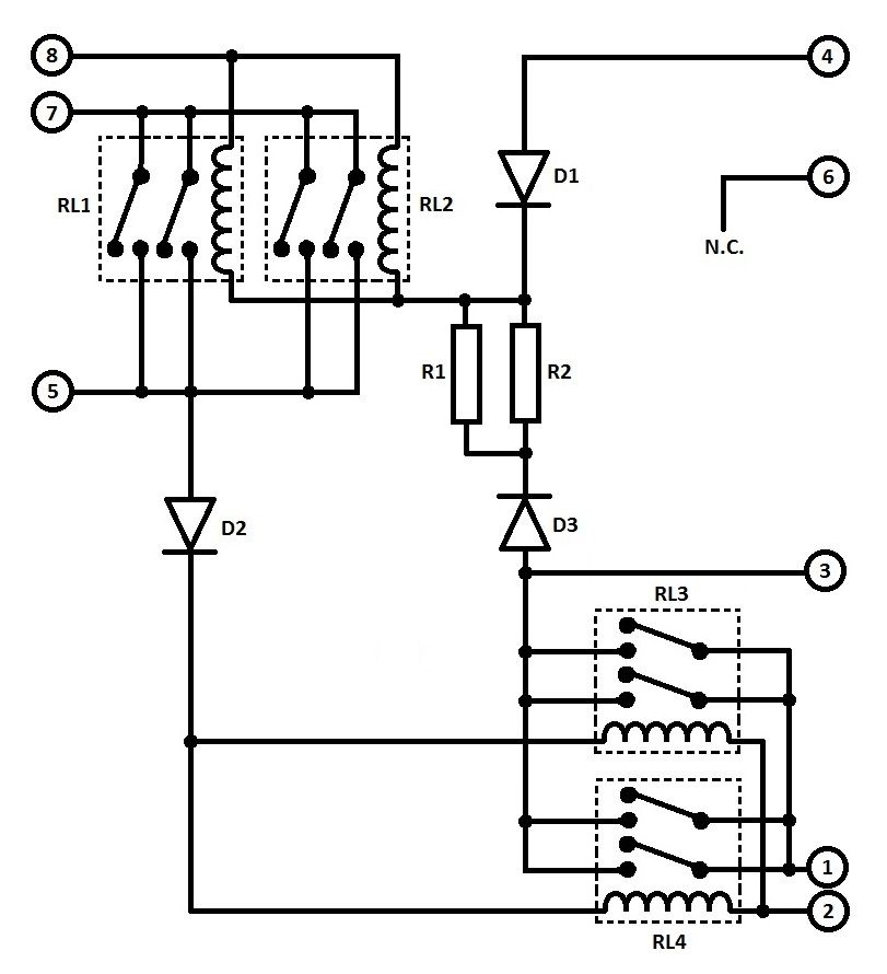
I then set about tracing the circuit design and metering all of the components, to see what was what. It’s been published elsewhere – and thankfully I came up with the same answer – but here’s my circuit of relay YWB10028:

The parts list for the circuit is as follows:
R1 - 43 ohm, 4 Watt wire-wound resistor
D1, D2, D3 – PEK8565 diodes
RL1 – SPNO relay, 28 ohm coil
RL2 – SPNO relay, 167 ohm coil
I then set about making some measurements. The diodes D1 to D3 (PEK8565) are either proprietary types (I assume “PEK” stands for Pektron) or just remarked standard types, just to throw people looking to reverse engineer the module off the scent. They meter out at about 0.8v forward voltage even under a few hundred milliamps of load, so there is something marginally “special” about them, in so much as the standard silicon types they resemble would have a forward voltage of 0.9v - 1.1v under normal operating conditions. Even so, a discrepancy of 0.1v doesn’t mean that much.
The relays are interesting. RL1’s coil has enough magnetic flux at 2.2v to pull its SPNO contacts closed – which is extremely sensitive. RL2’s coil operates its contacts at 5.5v – still very low. After all, this is an automotive relay – so why have coils that will activate at 2.2v and 5.5v and probably hold the relay on after activation at lower voltages than these??
I reassembled the relay but didn’t put it back into its housing. Instead, I attached wires to RL1’s and RL2’s coil pins and plugged it back into the car, so I could meter what the coil voltages were under starting and running conditions.
RL1’s coil receives 4.33v when the ignition switch is turned to the second (“run”) position. This is when you hear the fuel pump whir into life to pressurise the fuel rail and the “check engine” lamp flashes up on the dashboard. During starting, the coil voltage spikes much higher – my meter couldn’t capture the peak reliably but I saw 8-point-something volts at least. During running the coil voltage settles at 5.3v. Clearly, this is a 5v relay given the way it is driven in the car.
The behaviour also gives a clue to the circuit design. Pin 3 is obviously a 12v (13.2v) signal which is diode-ORed in with the 5v drive from pin 4’s signal to hold the relay on. Pin 3’s signal runs through the 43-ohm resistor R1, thereby forming a potential divider with the coil. So with RL1’s coil being 28 ohms, this would mean the coil voltage is notionally [28 / (28+43)] * 13.2, which equals 5.2v. Clearly the circuit has been dimensioned to ensure a secondary 5v drive from a 12v source on pin 3 to supplement the drive from pin 4 and guarantee a reliable start.
RL2’s coil voltage was measured to be 10.7v with the ignition switch in the second position and the check engine light / fuel pump on. It then rises to 11.6v after the pump switches off. During starting, the relay coil voltage dips to 6.7v and after starting rises to 12.96v.
Therein are some other reasons why the circuit has been dimensioned the way it has. Honda was obviously paranoid about ensuring the car started cleanly and reliably, worrying about battery voltage droop caused by the cold-cranking amps drawn by the starter motor.
So the fact the relays have very low activation voltages isn’t surprising. Moreover, under normal running conditions the relay coil impedances are so low, the magnetic flux must be holding those contacts more tightly together than is really necessary – but I suppose “reliable” is what you’d say.
Furthermore, the low impedance/resistance design of the circuit provides more answers as to why dry joints are more likely to develop. At 5v, RL1’s relay coil will dissipate 0.89 Watts. RL2’s relay coil at 13.2v will dissipate 1.04 Watts. R1 will dissipate 1.21 Watts, D1 will dissipate 0.14 Watts, D2 will dissipate 0.07 Watts and D3 will dissipate 0.18 Watts. Adding all this up, you get a total power dissipation in the relay of around 3.5 Watts. Now 3.5 Watts may not sound like much compared to a 21 Watt indicator bulb or a 55W headlamp bulb, but it’s notable. If you don’t believe me and you have a 216 or 416, detach the relay from the centre console where it is located and have it hang freely in the passenger foot-well, still connected to the car’s loom. Now go for a drive. You don’t have to be driving for more than 10 minutes to feel the heat build-up in the relay. Stop the car and clasp it in your hand – you wouldn’t expect a relay to feel that warm. The problem is – the warmth you feel is just the plastic case and it isn’t too bad in all honesty. But if that’s the temperature of the outer casing, which is insulating plastic and separated by an air gap with the components inside, the question becomes - what temperature do the relays, resistors and diodes reach inside? And more precisely, how hot do the solder joints get? The answer is – too hot. All that temperature cycling from cold start to hot driving will fatigue the solder joints after a while. Moreover, the currents being switched are appreciable – and I know from my own experience of circuit design, relying just on soldering for high current signals and fast switching won’t work in the long run. You need mechanical fastening (e.g. crimping or wire-wrapping) and soldering to make a reliable joint under these circumstances.
So the irony is – the relay looks to have been designed electrically to be ultra-reliable and faultless in operation. But the dimensions of the components and the current flows and power/heat dissipation they cause mean long-term solder joint fatigue becomes the issue, creating something which is a weak point in the reliability of the car.
The question is – if you want to replace the standard relay in our cars with something more reliable, given all this information, how do you go about it?
I’m firmly of the opinion that if you’re seeking to replace a circuit, you should look to dimension any new design in a way that is as close as possible to the original, or “within expected tolerances.” I couldn’t be certain the ECU didn’t need the relay coil signal paths to be the resistances they are – the relay might form part of a larger passive network in the ECU which is current-sensing to determine correct operation, for example.
Yet at the same time, any replacement circuit using the same design would get as hot as the original - notwithstanding the fact that better / more reliable construction techniques could be used.
The first problem was the relays. You can’t buy relays with 5v and 12v coils having such low nominal impedances. I looked through plenty of online catalogues – then I found a series of relays by arguably the best manufacturer around – Schrack, based in Austria. There were two parts in their compact PCB mounting range with specifications that seemed to be acceptable – the operating voltage on the 5v version was 3.5v for example – not the 2.2v of the Pektron component, but the car never expects the relay to operate anywhere near this point. In addition, the relay coils were low impedance but still twice that of the Pektron components at 62 ohms for the 5v model and 360 ohms for the 12v model.
I could have decided to connect parallel resistors across the relay coils to reduce their impedances. But then I thought – they’re actually almost exactly double the impedances I need, so why not just parallel up two relays instead? This would mean each relay only dissipates half the power of the original design, so they wouldn’t get anywhere near as hot. Twice the surface area of a single relay and twice the heat capacity too! Local heating of components and the circuit board / solder connections would be eliminated. Plus, the additional contacts operating in parallel would mean an ultra-reliable very high current switching action. The final effective coil resistances would be 31 ohms and 180 ohms, compared to the original design’s 28 ohms and 167 ohms. This, I believed, was acceptable – as it’s about a 10% difference and would be within expected tolerance. Being on the high side (31 instead of 28 and 180 instead of 167) the currents and heating would be reduced further too.
So that’s what I did. I also decided the 43 ohm 4 Watt resistor could be replaced by two 82 ohm resistors in parallel, giving 41 ohms effective resistance. I chose 3 Watt types, giving 6 Watts of power handling in total – 50% up on the original design. And again, 2 components not 1, so half the power dissipation in each.
Here’s my replacement circuit:
Note that the relays I’d found were DPNO and DPCO types, so I could use both poles of the two relays to provide 4 switched contacts in parallel. The relay contacts are rated 8 Amps, which is more than enough – so 4 in parallel is excessive – but reliable.
I had a project box in mind, small enough to fit on the original bracket and in the same position on the centre console. I was restricted on the size of board I could use as space was at a premium, but I managed to design a suitable layout. The board still needed its corners chamfering (in fact, I had to lose one hole on the top two corners, but they’re not used).
Here’s the Vero-board layout of my design showing the trackside including the track breaks that need to be made, the component side and the wiring diagram. The board actually has horizontal symmetry with respect to the track breaks, which makes construction a little easier.
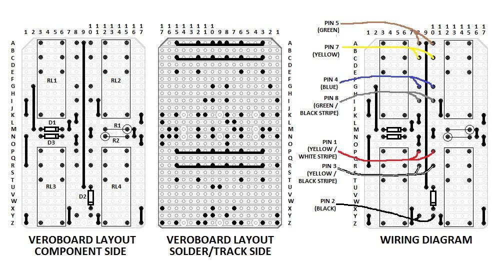
Note that on the track side, I made provision for the high-current switching paths by allowing for an additional copper wire to be soldered along the 4 tracks that carry the signals for pins 1 and 3 and pins 5 and 7 on the Rover loom. Standard Vero board tracks are probably good for 1 Amp at most, but I’d specified 0.8mm diameter copper wire which I’d worked out would provide more copper between the pins that matter than the original circuit board. Basically, the original PCB has 1-ounce copper (having mic’d it), so the tracks would have to be 15mm wide or thereabouts for there to be more copper on the original design – and there’s no way the current-carrying tracks on the original PCB are wider than 10mm let alone 15mm at their narrowest points.
The shopping list of parts for my design was as follows:
RL1, RL2
TE Connectivity RTE24005 5V 8A DPST NC Relay RTE24 360R coil
Rapid Electronics Order Code: 60-1270
QTY: 2
RL3, RL4
TE Connectivity RTE24012 12V 8A DPCO Relay RTE24 62R coil
Rapid Electronics Order Code: 60-1250
QTY: 2
R1, R2
TruOhm KNP Series 82R 5% 3W Axial Wirewound Resistor
Rapid Electronics Order Code: 62-1369
QTY: 2
D1, D2, D3
DC Components 1N4001 1A 50V Silicon Rectifier Diode
Rapid Electronics Order Code: 47-3130
QTY 3: (MOQ 5)
Stripboard 95 x 127mm
Rapid Electronics Order Code: 34-0515
QTY: 1
Single Sided Terminal Pins Pack Of 100
Rapid Electronics Order Code: 34-0610
QTY: 1
The wiring for the module is 1 metre of 7-core high-current multi-core cable from Ebay:
http://www.ebay.co.uk/itm/161809822693
I stripped the cores from the cable, cut them to about 30cm, stripped and tinned the ends and wired up the finished module. Note that I made provision for 2 solder pins for each wire to the board – again, doubling up everything to make sure the design is as reliable as possible. This meant the stripped ends to the boards were actually divided into two bunches of strands each before twisting and tinning – so one wire solders to both pins.
Here’s a photo of the finished replacement relay:

And the track side showing the high-current fortification of the 4 tracks that need it using 0.8mm diameter tinned copper wire:

Connecting the replacement relay to the car may appear to present a problem, until you realise the metal blades on the original are just replicating 6.3mm spade terminals and the plug on the Rover loom is just 8 off 6.3mm spade receptacles crimped onto the ends of the cable and held in a plastic housing. So I just purchased some standard 6.3mm spade crimp terminals:
Red 6.3mm Male Tab Connector - Pack of 100
Rapid Electronics Order Code: 33-1057
1 pack of 100
Here’s the temporary lash-up with the spades connected:

I checked the design off the car. The circuit appeared to work as it should – the relays operated with the correct voltages applied to the appropriate pins, there were no shorts and the relay contacts closed and made contact between the pins they were supposed to.
So I gingerly wired up the new relay to the car and turned the key. Success! The car started on the button and carried on running. I tried it several times…
The next thing to do was to put in in a nice box – the one I’d chosen originally, which is this little item, also from Rapid:

Miniature ABS Box Black 50x28.5x74
Rapid Electronics Order Code: 30-3538
QTY: 1
It just needed a hole in the side for the 7 wires to come out, fitted with an 8mm I/D grommet – I bought a 10-pack from Maplin Electronics, part code QT94C. I had to cut the 7 spade terminals off the wires so they’d poke through the grommet. The assembled board fitted where it touched – I had to pull the wires through the grommet and guide the board in, sliding the grommet-side edge down into the case until the other side dropped in.
Here’s the finished relay boxed, before the lid went on:

Then I just re-crimped spade terminals onto the wire ends. I also printed out some small adhesive labels that I wrapped around the wire ends, carrying the pin number and the colour of the Rover loom wire each spade had to connect with – not all of the wires in the cable I’d used had the same colour as the ones in the car.
The finished, boxed relay with a wire-tie around the wires at the relay end:

Next to the original relay, showing it to be a similar width and height, including the connector block:

Next to the original relay – somewhat slimmer in profile.

If you want to attach it to the car, you’ll need a replica bracket (which you could make by taking a paper template of the original) or an original bracket.
Taking a bracket off the original relay is easy enough. You simply insert a flat-blade screwdriver behind the bracket so the casing flexes and the metal slides over the retaining lug – as shown below:

I had bought some M3 nylon nuts, bolts and washers to attach the original bracket to the car. I was planning on drilling 4 holes in the end-plate. Using nylon fixings, I wouldn’t have had to worry about metal inside the casing having to be insulated from the circuit board. However, I just decided to go with my favourite fix – GTPro double-sided acrylic adhesive foam tape. That stuff is stickier than anything I know, so with less than a square inch of it used, the bracket was on and not coming off.
The finished relay, boxed, with labelled wiring and bracket, ready to go back onto the car:

So there you go:
1. Everything you did want to know,
2. Everything you didn’t want to know,
3. Everything you knew you didn’t know,
4. Everything you knew you knew,
5. Everything you didn’t know you knew,
6. And everything you didn’t know you didn’t know
…about the Honda main relay, in one easy to read post.
I think that puts the subject well and truly to bed as they say, but I’d be interested in your comments.
That’s the problem with cars – everything, even the tiniest aspect of them, once examined, explodes into a myriad of detail that requires infinite analysis – just so you’re certain of what’s actually going on.
I’m exhausted after that write-up, so I won’t be attempting another “build your own” for a while. The next one will probably be “How to 3D print a new K series engine.” That should be fun